
Anyone who's spent time around a die shop has heard the line: "bearing length controls metal speed." It's true — but said that way, it's a rule to memorise, not something you actually understand. And the difference matters, because die correction only gets fast and reliable once you understand why a longer bearing slows metal down, not just that it does.
This post goes one level deeper than a typical extrusion overview — straight into the friction, geometry and flow-balancing logic that die designers actually use.
What Exactly Is a Die Bearing?
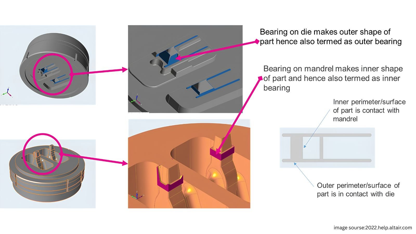
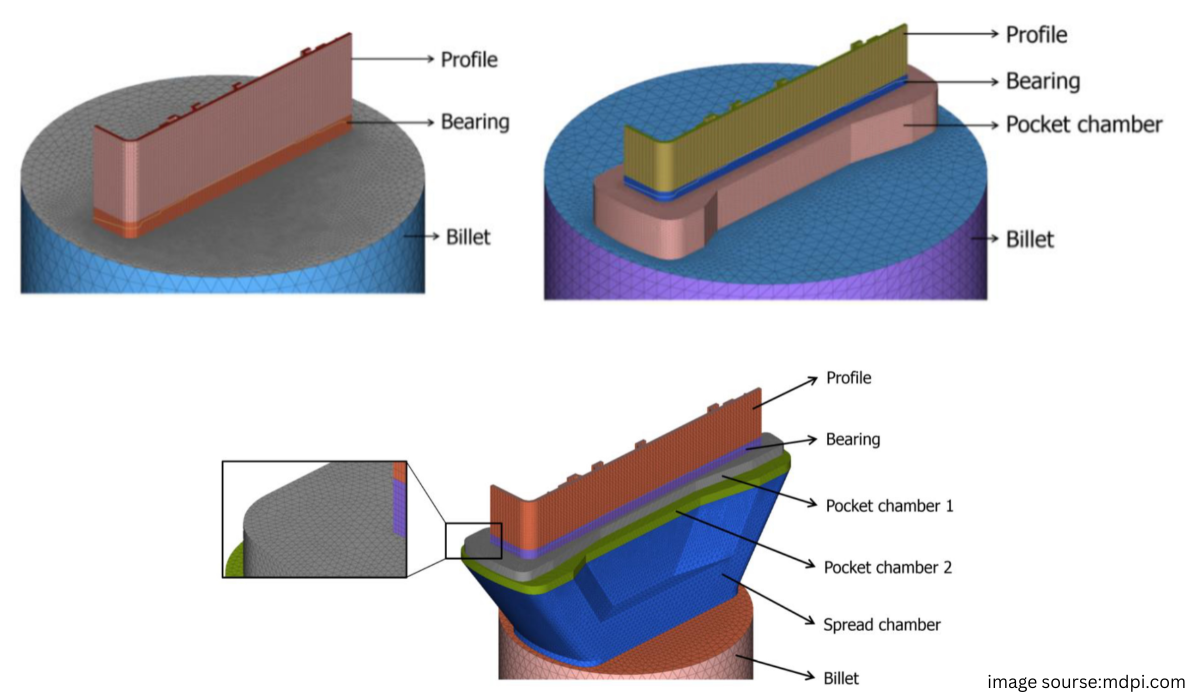
The bearing — also called the die land — is the final straight channel that hot aluminium travels through immediately before leaving the die. Picture the full flow path like this:
Billet → Die entry / pocket → Bearing channel → Profile exits
Everything upstream of the bearing (the die entry, any pockets or sink-ins) shapes how metal approaches the die opening. The bearing is the last point of control before the metal becomes the finished profile — the die designer's final opportunity to correct or fine-tune how fast each part of the section is moving.
Why Does Bearing Length Control Flow Speed?
The short version everyone learns first:
Shorter bearing → less flow resistance → faster local metal flow.
But here's the actual mechanism behind that rule.
Picture aluminium passing through two bearing channels of different lengths:
- Channel A — 5 mm long
- Channel B — 15 mm long
Metal travelling through the 15 mm channel stays in contact with the die's steel surface over three times the distance. At the hot-aluminium-to-tool-steel interface, that contact zone is under high pressure with significant shear interaction — the aluminium is essentially "dragging" against the die wall the entire time it's inside the bearing. A longer contact length means more total friction and shear resistance acting against that portion of the metal as it tries to move forward.
So the chain of cause and effect looks like this:
Bearing length increases → contact/shear-affected path length increases → resistance to local movement increases → local exit velocity decreases.
Reduce the bearing length at a given position and you reduce that resistance, letting metal move faster through that specific part of the die. It's a purely local effect — you're not changing the whole die's behaviour, just the behaviour at that one point around the profile's perimeter.
But Why Do We Need to Slow Anything Down in the First Place?
This is the part that actually explains why bearing length matters at all — because aluminium does not naturally want to flow at the same speed everywhere in a complex profile.
Take a simple example: a profile with one thick section and one thin leg.
Thin leg → generally offers more geometric resistance → tends to flow slower.
Wall thickness isn't the only factor — a section's position relative to the die and container, how much perimeter it has relative to its area, and the upstream die geometry (pockets, feed paths) all influence how eagerly metal flows into and through that part of the die. This is exactly why flow balancing becomes critical for profiles with uneven thickness or complex, multi-limbed geometry.
Now imagine both regions are part of the same profile, exiting through the die at the same time. If left uncorrected:
Thick area → fast. Thin area → slow.
The fast-moving section pulls ahead while the slow section drags behind — but they're physically joined as one piece of metal. The result is exactly what you'd expect from pulling one end of something faster than the other: bending, twisting, dimensional variation, and general distortion in the finished profile.
The Die Designer's Fix: The Bearing Curve
This is where bearing length stops being a fixed dimension and becomes an active design tool. The die designer assigns different bearing lengths around different parts of the profile opening, specifically to counteract the natural flow imbalance:
Slow-flowing area → shorter bearing → less resistance → flow speeds up to match.
The target is uniform exit velocity — not uniform bearing length. That distinction is one of the most important things to internalise about die design: the goal was never "make all the bearings the same length." The goal is "make all the metal exit at the same speed," and bearing length is simply the knob used to get there.
When a die designer maps out bearing lengths around the entire profile perimeter — longer here, shorter there, based on where metal naturally wants to move fast or slow — that map is called a bearing curve. It's essentially a record of two decisions repeated around the whole section:
Where should we resist the aluminium more? Where should we let it flow more freely?
The simplest way to think about it:
Fast area → apply more brake → longer bearing.
Slow area → release the brake → shorter bearing.
A Real Example: Heat Sink Extrusion
Heat sinks are one of the clearest illustrations of this principle, because the geometry makes the flow imbalance obvious even to someone new to die design.
A typical heat sink profile has:
- A thick base running across the width of the profile
- A row of thin, closely spaced fins standing up from that base
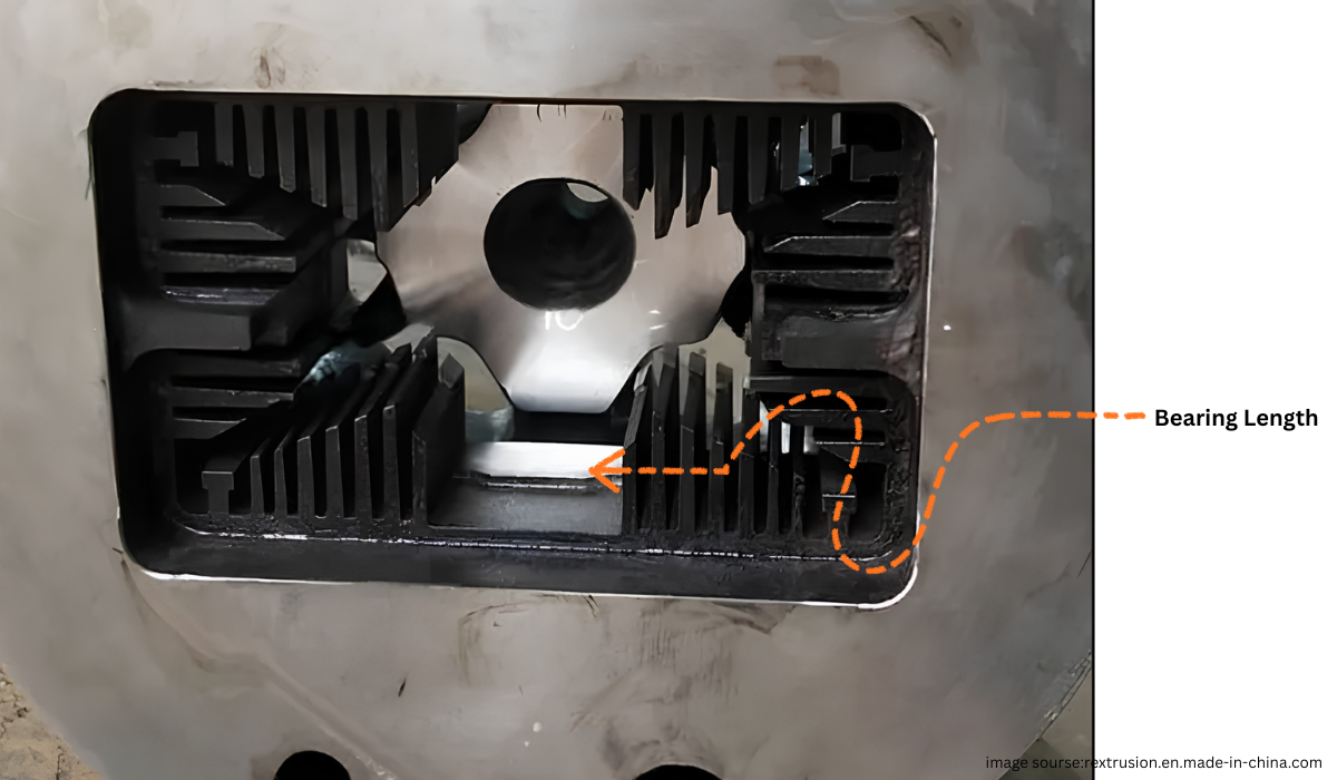
The base and the fins do not naturally want to flow at the same rate. The substantial thick base has far less resistance to overcome than the narrow, tightly packed fins. Left uncorrected, the base tries to race ahead of the fins during extrusion.
If that happens, the base effectively drags the whole profile forward while the fins lag behind, leading to distortion and non-uniform exit velocity across the section. So the die designer has to actively slow the base down and/or help the fins keep pace — typically by giving the base a considerably longer bearing than the fins, and in more difficult cases, combining this with upstream flow-control geometry like pockets or sink-ins to redirect metal volume before it even reaches the bearing.
For complex, large, or multi-cavity profiles, this balancing act often can't be solved by bearing length alone — which brings us to an important limitation.
An Important Correction: Bearing Length Isn't the Whole Story
It would be a mistake to teach — or believe — that bearing length is the single factor controlling metal flow in extrusion. It's one of the primary tools, but real die behaviour is shaped by many factors working together:
- Profile thickness and overall geometry
- Position of each section relative to the die and container
- Pocket or sink-in geometry upstream of the bearing
- Porthole and welding-chamber design, for hollow profiles made on porthole dies
- Billet, container and die temperature
- Extrusion (ram) speed
- The specific alloy's flow stress behaviour at temperature
- Friction and contact conditions at the tool-metal interface
- Die deflection under load
For hollow profiles produced through porthole dies specifically, achieving uniform exit velocity depends on balancing port geometry and welding-chamber design together with bearing length — bearing length alone cannot fix a poorly balanced porthole layout.
So the more accurate, more useful way to state the principle is:
One More Subtlety: Longer Isn't Always Proportionally More Restrictive
Here's a detail that surprises a lot of people once they've grasped the basic rule: bearing length doesn't restrict flow in a simple straight-line relationship forever. Bearing geometry and contact conditions matter just as much as raw length.
In certain bearing designs — for example bearings with a relief or taper built in after the initial contact zone — the aluminium can actually lose continuous contact with the bearing wall partway through the channel. Once that happens, simply making the bearing longer doesn't necessarily add more flow resistance the way it would in a straight, fully-contacting bearing.
Which means the real engineering question a die designer asks isn't only "how long should this bearing be?" It's also "what is actually happening to the aluminium as it travels through this specific bearing channel — is it staying in full contact, or has the geometry let it separate from the wall?"
Bringing It Together
Bearing length works as a flow-control tool because of a simple physical chain: more contact length means more friction and shear resistance, which means slower local exit velocity. Die designers exploit that relationship deliberately, mapping out a bearing curve around a profile so that naturally fast areas get slowed down and naturally slow areas get sped up — with the single goal of uniform exit velocity across the whole section.
But bearing length is a tool within a larger system, not a standalone switch. Real die correction work also has to account for pocket geometry, temperature, speed, alloy behaviour, and — in hollow dies — porthole and welding-chamber balance. Understanding the "why" behind bearing length is what turns a rule you memorise into a principle you can actually apply when a new profile doesn't behave the way you expect.