
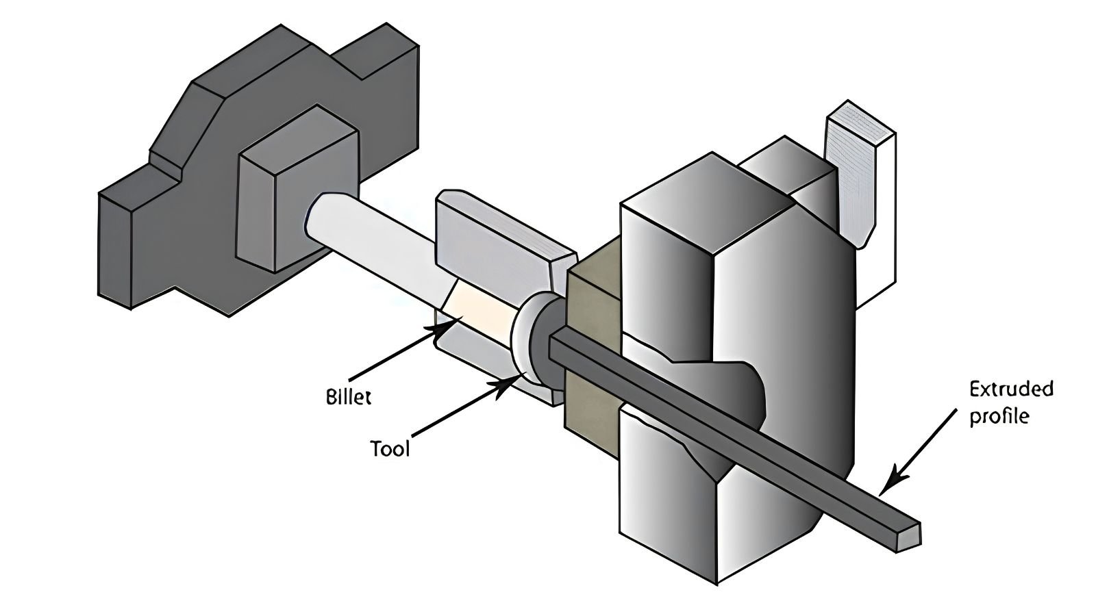
Ask most people how aluminium extrusion works and you'll get some version of: "heat the billet, push it through a die, profile comes out." Technically correct. But it skips over almost everything that makes the process interesting — and almost everything a die designer, quality engineer, or press operator actually has to think about every single cycle.
Here's the part most explanations leave out:
This post walks through what's actually happening to the metal, stage by stage, inside a conventional direct extrusion press.
Stage 1 — The Heated Billet Enters the Container
Before extrusion even starts, both the billet and the tooling (container, die, dummy block) are brought up to temperature. For most aluminium alloys, billet temperature typically falls somewhere in the range of roughly 375°C to 500°C, depending on the alloy family and the profile being produced.
At this temperature aluminium is far below its melting point. What's happening is a change in how easily the metal deforms — hot aluminium becomes dramatically softer and more workable under compressive load, without losing its solid state. The billet is loaded into the container, with the die and bearing assembly waiting at the front, and the ram (driven through the stem and dummy block) is positioned to begin applying force.
Key point to remember: nothing is molten at any stage of this process. The entire transformation from cylindrical billet to finished profile happens through solid-state plastic deformation.
Stage 2 — Upsetting: The Billet Gets Shorter and Wider First
This is the part almost nobody talks about, and it's one of the more interesting mechanical details of the whole process. When the ram first starts moving, metal does not immediately start coming out of the die.
Instead, the billet is squeezed between the ram and the die face. Since it can't go anywhere forward yet, it does the next best thing under compression — it gets shorter along its length and bulges outward radially, expanding until it presses firmly against the container wall. This is generally referred to as the upsetting or filling stage.
In sequence:
Ram advances → billet compresses axially → billet expands radially → billet fills the container completely.
Only once the billet has fully filled the container cross-section does the system move toward the next phase — because until then, the metal has an "easy" direction to move (outward) that doesn't require pushing through the die at all.
Stage 3 — Pressure Builds Toward Breakthrough
With the billet now fully confined — container wall on the outside, die face at the front — the metal has run out of easy directions to move. The only path left is through the openings in the die.
But that path is resisted by several things at once: the force needed to plastically deform the metal itself, friction between the billet surface and the container wall (which is significant in direct extrusion, since the whole billet mass slides against the container as it's pushed forward), and the geometric restriction of the die opening.
As the ram keeps pushing, pressure inside the container climbs rapidly. This builds toward what's called breakthrough — the point where pressure finally exceeds the combined resistance and metal begins flowing through the die in a sustained way.
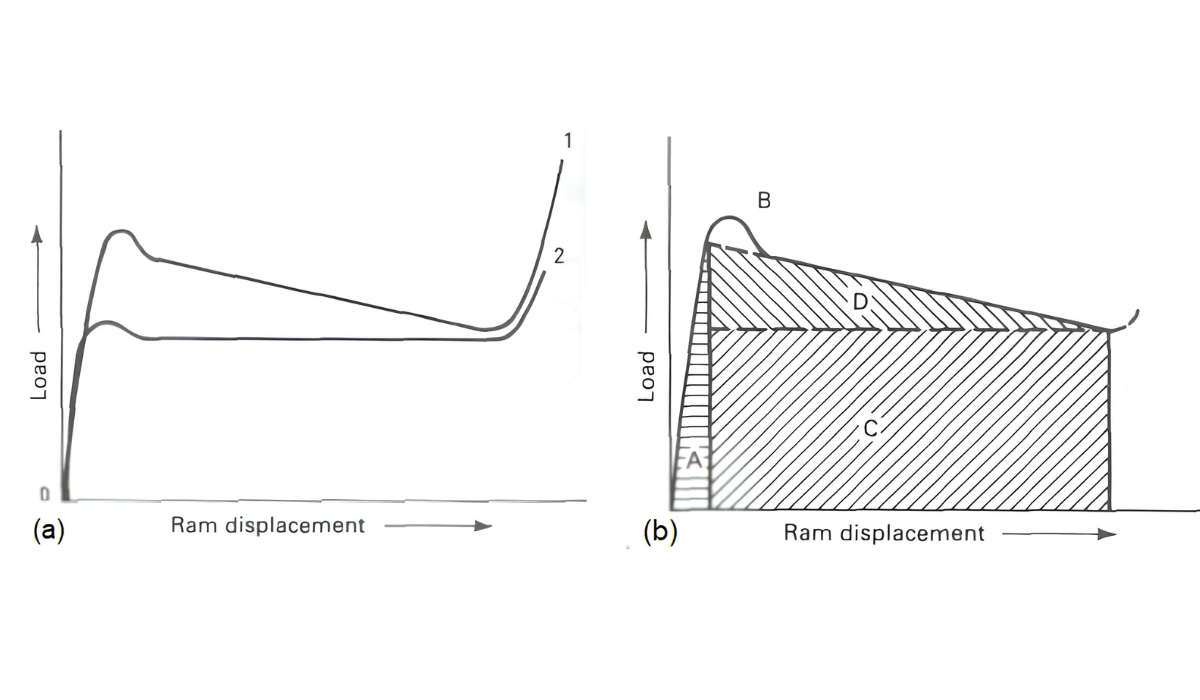
Typical press-load behaviour: pressure rises sharply during filling and breakthrough, then settles into a lower, steadier level once flow is established.
This pressure curve is one of the most useful things to understand as an engineer — it tells you almost everything about how a press cycle is behaving: billet condition, container wear, die design, and whether something is fighting the flow more than it should.
Stage 4 — Metal Starts Flowing Toward the Die
Once breakthrough is reached, aluminium has only one place left to go — into and through the die. But here's the part that separates a basic explanation from a real engineering one: the metal inside the billet does not all move at the same speed.
Friction against the container wall, the geometry of the die face, and local resistance all combine to create very different flow velocities across the billet cross-section. Metal near the centre, aligned with an open die passage, tends to move faster. Metal near the container corners and die face — where friction and geometry fight it the most — moves much more slowly. In some cases, that metal barely moves at all relative to the rest, forming what's commonly called a dead metal zone.
This uneven flow is exactly why die design isn't just about cutting the profile outline into a steel block. A die designer is constantly managing velocity distribution — trying to make metal from very different starting positions in the billet arrive at the exit at roughly the same speed.
Stage 5 — The Die Takes Control of Flow
This is where die design earns its complexity. Different areas of a profile naturally want to flow at different rates — a thick section of the profile behaves very differently from a thin leg right next to it, and a section positioned near an easy feed path behaves differently from one tucked in a corner.
To manage this, die designers use flow-control features such as pockets (sink-ins machined into the die face) that redirect and regulate how much metal reaches each part of the opening, improving uniformity of flow before the metal even reaches the bearing.
Then comes the bearing — the straight-walled section of the die opening that the metal travels through just before exiting. It's tempting to think of the bearing as simply "the wall that shapes the profile," but its real job is far more precise: it provides fine frictional control over exit velocity.
In simple terms: fast-flowing areas of the profile get a longer bearing to hold them back; slow-flowing areas get a shorter bearing to help them keep up. The goal is a profile where every part of the cross-section exits at close to the same speed — which is what keeps the profile straight, dimensionally correct, and free of twist or bow.
Stage 6 — Hollow Profiles: Splitting and Rejoining the Metal
For solid profiles, the story above covers most of it. But hollow profiles — box sections, tubes, multi-chamber shapes — involve something genuinely fascinating, and it deserves its own explanation beyond what we can cover fully here.
A common beginner assumption is that there must already be a hole in the billet to produce a hollow section. There isn't. With a conventional porthole die and a solid, un-pierced billet, the process instead works like this:
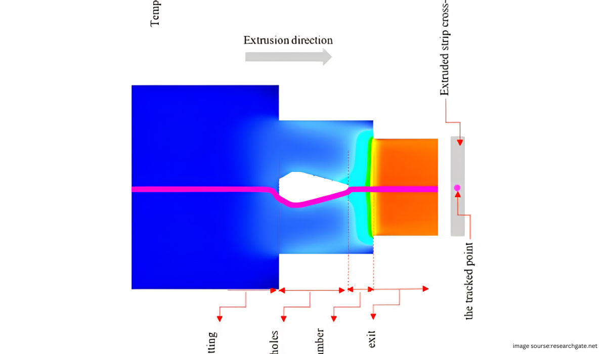
A single solid billet is forced against a die containing internal bridges. The metal stream is physically split into separate flows that pass around these bridges through openings called portholes. Once past the bridges, under continuing high pressure and temperature, these separated streams are pushed back together inside a welding chamber before the now-reunited metal exits through the final bearing as one continuous hollow profile.
The seams where these streams rejoin become longitudinal weld lines running the length of the hollow profile — a detail with real implications for section strength and surface finish, and a topic we'll cover in a dedicated post.
Stage 7 — The Profile Takes Final Shape
As the metal passes through the die bearing, it takes on the exact cross-sectional geometry cut into the die — this is the point where "extrusion" becomes visually recognisable as a finished profile shape.
It's worth pausing here to appreciate the scale of deformation involved. A typical billet cross-section is dramatically larger than the cross-section of the profile it produces. The ratio between the two is called the extrusion ratio:
A higher extrusion ratio means more deformation is packed into the same billet length — which generally means higher required press load, more heat generated by deformation, and tighter demands on die design to control flow evenly. Extrusion ratio is one of the first numbers experienced die designers check when planning tooling for a new profile.
Stage 8 — Temperature Doesn't Stay Constant
The billet enters the press at a controlled temperature, but that temperature does not remain fixed throughout the cycle. Plastic deformation and friction both generate heat as the metal is forced to change shape and slide against the container and die surfaces. This means the aluminium's temperature at the die exit is the combined result of several factors:
- Initial billet preheat temperature
- Container temperature and condition
- Ram speed
- Die design and flow resistance
- Billet dimensions and extrusion ratio
This is exactly why "just increase ram speed to push out more profile per hour" is risky advice on its own. Faster ram speed generates more deformation heat, which can push exit temperature above the safe process window for that alloy — leading to surface tearing, hot shortness, or other defects. For many heat-treatable 6xxx-series alloys that rely on press quenching, die-exit temperature is also directly tied to whether the profile achieves proper solution heat treatment in that same step — making exit temperature control a metallurgical concern, not just a productivity one.
Stage 9 — Extrusion Settles Into a Steady State
After the initial filling, breakthrough, and transient flow have passed, the process moves into a more stable, established condition. Interestingly, the pressure required to keep pushing metal through generally decreases from its earlier peak as extrusion continues — largely because the billet is getting shorter, which changes the contact length (and therefore total friction) between the remaining billet and the container wall.
This gives the whole cycle a recognisable shape when you plot pressure against ram travel: a rise during filling, a peak at breakthrough, a decline and stabilisation during steady-state flow, and — as we'll see next — a final rise near the very end of the cycle.
Stage 10 — The Butt End and Cycle Restart
The press does not push the entire billet through the die. As the remaining billet gets very short, flow becomes increasingly constrained and press load rises again near the end of the cycle. Rather than forcing this last portion through — which would risk defects and unnecessary tooling stress — a small remainder called the butt (or discard) is deliberately left behind.
The finished profile is separated from the die, the butt is sheared off and set aside for recycling, and the press resets to load the next billet. The entire ten-stage sequence then repeats, cycle after cycle, for the next billet.
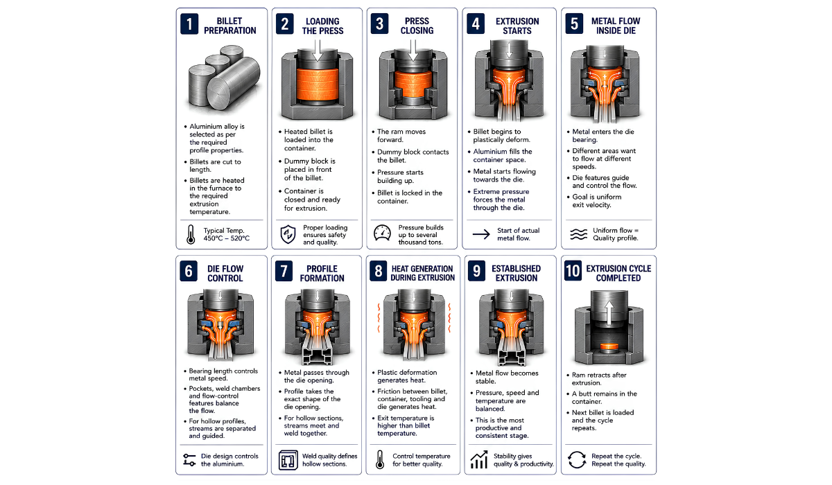
The Full Sequence, In One View
Why This Matters Beyond Theory
Understanding these stages isn't just academic. Nearly every practical extrusion problem traces back to one of them:
- Twist or bow in a profile? Often an uneven exit velocity problem — back to Stage 5 (bearing balance).
- Surface tearing or blistering? Frequently an exit-temperature problem — back to Stage 8.
- Weld seam weakness in a hollow section? Traces to welding chamber pressure and temperature — Stage 6.
- Inconsistent press productivity? Often a breakthrough and steady-state pressure issue — Stages 3 and 9.
The next time someone reduces this whole process to "billet goes in, profile comes out," you'll know exactly how much engineering is packed into that single sentence.